
AC vs DC: Why Industry Uses 24 VDC and Electronics Use 5 V or 3.3 V
A practical guide to AC and DC, why 24 VDC dominates industrial control, and why modern electronics use 5 V, 3.3 V and lower supply rails.
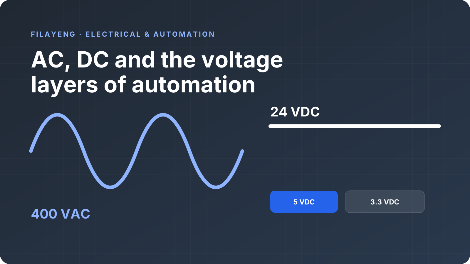
Open an industrial control cabinet and you may find 400 VAC, 230 VAC, 24 VDC, 5 VDC and 3.3 VDC in the same enclosure. That raises an obvious question: why not run everything from one voltage?
Because turning a motor and reading a sensor solve very different engineering problems. Power distribution needs manageable current, cable size and losses. Field signals need to survive electrical noise. A microcontroller needs to switch millions of tiny transistors without wasting power. Each voltage level is a practical fit for a different layer of the system.
This guide builds a mental model for those layers instead of treating the numbers as facts to memorize.
What are AC and DC?
With DC (direct current), voltage polarity remains consistent over time. An ideal 24 VDC supply keeps its +24 V terminal positive relative to its 0 V reference. The load current may change and the supply can contain ripple or switching noise; DC does not have to be a mathematically perfect flat line. Its polarity simply does not reverse periodically in normal operation.
With AC (alternating current), instantaneous voltage and polarity change periodically. Utility voltage is approximately sinusoidal. The nominal mains frequency in Türkiye is 50 Hz, so the waveform completes 50 cycles each second and crosses zero twice per cycle.
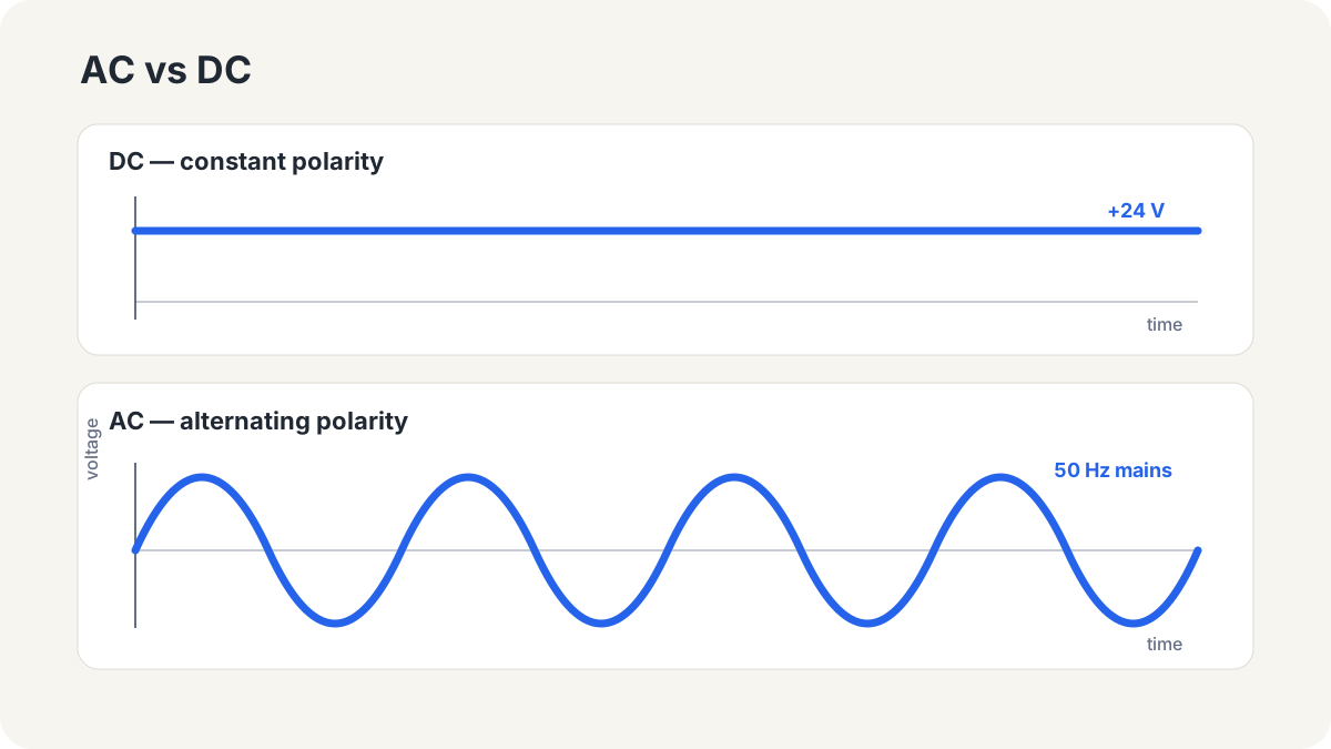
The familiar 230 V mains figure is an RMS value, not the sine wave’s peak. RMS expresses the DC voltage that would produce a comparable heating effect in a resistive load. A meter reading of 230 VAC does not mean the instantaneous waveform stays at 230 V.
Why is AC used for the grid?
For a simple DC load, power is:
P = V × I
Raising voltage reduces the current required to carry the same power. Approximate cable voltage drop is V_drop = I × R, while resistive line loss is:
P_loss = I² × R
Halving current reduces loss in the same resistance to one quarter. This is the core reason bulk electrical energy is transmitted at high voltage.
The transformer was central to the technical and historical success of AC networks. It can step AC voltage up or down efficiently with no moving parts: voltage is raised for transmission to reduce current and losses, then lowered near users. Modern power electronics also makes high-voltage DC transmission practical and attractive for certain links. It is therefore too simplistic to say that AC is always superior to DC. Network architecture, conversion, protection and the installed equipment ecosystem all matter.
Why do factories have both 400 VAC and 230 VAC?
A common low-voltage three-phase system uses conductors identified as L1, L2, L3, N and PE:
- L1, L2 and L3 are phases separated by 120 electrical degrees.
- N is the neutral conductor.
- PE is protective earth.
In this context, voltage is approximately 400 VAC phase to phase and 230 VAC phase to neutral. Actual values vary with supply and load conditions.
Three-phase power creates a natural rotating field in motors and distributes substantial power efficiently. The 230 VAC phase-to-neutral supply may serve cabinet outlets, lighting, power supplies and smaller single-phase auxiliaries. The device nameplate, datasheet and system design determine the correct connection.
Where is 400 VAC used?
Typical three-phase loads include:
- motors, pumps, compressors and fans
- variable-frequency drives and some servo drives
- appropriately designed three-phase heater banks
- CNC machine power circuits
- larger machine and process loads
Consider a deliberately simple scale calculation. Supplying a 3 kW load from an ideal 24 V source would require:
I = P / V = 3000 / 24 ≈ 125 A
This ignores efficiency, power factor and starting current; it is not a design calculation. It shows why voltage matters. Carrying 125 A requires substantial conductors, switching devices, terminals and thermal management. Higher voltage lets the power layer deliver the same power at a more manageable current.
Why does industry use 24 VDC?
24 VDC is a useful compromise between power delivery and reliable field signalling. Its popularity is not explained by one feature alone; lower shock risk, noise margin and a broad device ecosystem reinforce one another.
A safety advantage—not a guarantee
In a properly designed circuit and suitable dry conditions, 24 VDC generally presents a lower electric-shock risk than 230 or 400 VAC. That is valuable around machine control and sensors. But 24 VDC is not harmless under every condition. Wet conditions, damaged skin, batteries or supplies capable of high fault current, short-circuit heating and arcs can still cause injury or fire. Isolation procedures, protection, suitable fusing and safe working practices remain necessary.
Better suited to field signals
Contactors, motor cables, solenoids and VFDs make a factory electrically noisy. A 1 V disturbance consumes a large part of a 0–5 V signal range. Relative to a 0–24 V signal it is smaller, and designers can provide wider input-threshold margins.
That does not make 24 V immune to interference. Cable routing, shielding, grounding strategy, input filters, reference integrity and EMC-aware construction still determine whether a system is reliable.
A standardized ecosystem
24 VDC variants are common among PLCs, digital I/O, proximity and photoelectric sensors, encoders, relay and contactor coils, solenoid valves and some HMIs. Because manufacturers support large 24 V product families, sourcing compatible power supplies, interfaces and spare parts is easier. A shared control voltage also simplifies cabinet design and troubleshooting.
Long cables and voltage margin
Long cables introduce resistance and collect interference from their surroundings. Compared with 5 V, a 24 V system has more allowance for cable drop and practical input thresholds. Cable size must still be checked against current and distance, including the pull-in or inrush demand of valves and relays.
A basic 24 VDC sensor and PLC input
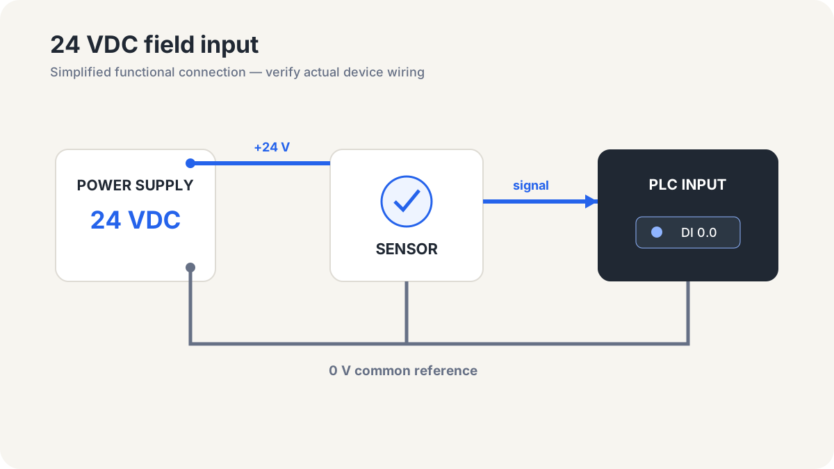
A simplified three-wire sensor connection looks like this:
+24 V ───────┐
             │ supply
          [ Sensor ] ───── signal ───── [ PLC digital input ]
             │                                  │
0 V ─────────┴──────────────────────────────────┘ common reference
The supply establishes a reference for the sensor and PLC input circuit. When the sensor detects its target, it presents the electrical state expected by the input, which the PLC interprets as logic 0 or 1. The real connection depends on whether the sensor and input are PNP or NPN. Sourcing, sinking, PNP and NPN deserve a separate article.
Does a PLC CPU actually run at 24 V?
A 24 VDC rating at the PLC power terminals does not mean its CPU core or memory runs directly from 24 V. The input stage commonly includes reverse-polarity, surge and overvoltage protection, filtering, DC/DC regulation and—depending on the product—galvanic isolation.
Internal converters generate rails such as 5 V, 3.3 V and 1.x V. A 24 V field input is current-limited and threshold-detected, often through an isolation stage, before reaching internal logic. 24 V is the robust field interface; the PLC CPU is low-voltage semiconductor electronics. Isolation and common-terminal arrangements vary, so the product documentation is authoritative.
Why is 5 VDC common in electronics?
Several ecosystems made 5 V durable:
- Classic TTL logic families operated around 5 V and left a huge installed base.
- Educational and prototyping boards such as the Arduino Uno made 5 V logic familiar.
- Traditional USB VBUS is nominally 5 V, influencing a large peripheral and module market.
- Many sensors, displays, relay boards and peripherals offer a 5 V supply option.
For low-power electronics, 5 V is easier to regulate and dissipates less power than using 24 V directly. It also provided useful noise margin for older logic families. Yet a board with a 5 V power input can still contain a 3.3 V processor. Never infer that every pin is 5 V tolerant from the supply connector alone.
Why is 3.3 VDC so widespread?
Modern ARM microcontrollers, ESP32 devices, many sensors, FPGAs and communication ICs use 3.3 V I/O. Smaller transistor geometries make high electric fields harder to tolerate, and internal core rails have moved even lower. In many products 3.3 V became a practical external I/O level between legacy 5 V interfaces and low-voltage cores.
Dynamic digital power is roughly related by P_dyn ∝ C × V² × f. With other variables fixed, reducing voltage can substantially cut switching energy—valuable for temperature, battery life and dense integration. Smaller signal swing can also reduce noise margin and complicate analog behaviour, so lower is not automatically better in every system.
What if 24 VDC is connected to a 3.3 V MCU pin?
Most 3.3 V microcontroller pins cannot tolerate 24 V. A direct connection can force excessive current through input protection structures, destroy the pin or MCU, and damage connected circuitry. Applying a signal while the MCU is unpowered can also back-power it through the input.
Depending on the requirements, an industrial input interface can use:
- a current-limited divider with clamping and transient protection
- a transistor stage or dedicated digital-input/driver IC
- an optocoupler or digital isolator
- a suitable level translator
- reverse-polarity, surge and ESD protection
A resistor divider looks simple but may not address thresholds, tolerance, transients, power sequencing or reference differences. Galvanic isolation is not mandatory everywhere; it becomes especially useful where ground-potential differences, safety goals or EMC requirements justify it. The engineering task is a complete input interface, not merely dividing 24 by a convenient ratio.
Where is 12 VDC used?
12 VDC is common in traditional automotive electrical systems, LED strips and lighting, small DC motors, fans, cameras and some electronic modules. A vehicle supply is not a constant 12.0 V: charging, cranking and transients create a wide and demanding operating range. A generic “12 V” label does not prove that a module is suitable for automotive use.
Why is 48 VDC becoming more visible?
Doubling voltage halves current for the same ideal power:
| Power | Voltage | Current |
|---|---|---|
| 480 W | 24 V | 20 A |
| 480 W | 48 V | 10 A |
Lower current can reduce conductor and connector demands as well as resistive losses. 48 V-class systems have a long history in telecommunications and now appear in PoE, robotics, some servo or distributed-power systems, and data-center architectures. “48 V” does not define one exact operating range or safety category; the actual system limits and equipment requirements matter.
How do AC and DC coexist in one cabinet?
A typical automation cabinet can be read as two major layers.
The power layer brings in 400 VAC and distributes it through switching and protection devices to a VFD, contactor, heater or motor. Some auxiliary loads use 230 VAC phase to neutral.
The control layer feeds an industrial power supply—often from 230 VAC—which produces 24 VDC for the PLC, sensors, valves, relays, I/O and compatible HMIs. Inside those devices, regulators create 5 V, 3.3 V and lower electronic rails.
These layers can share an enclosure, but conductor separation, protection, shielding and grounding are engineered deliberately.
Field example: PLC, contactor and a 400 V motor
A motor may run from 400 VAC while its contactor coil runs from 24 VDC:
PLC output → 24 VDC contactor coil → mechanical action → power contacts → 400 VAC motor
The PLC output does not carry motor power. It energizes the coil directly or through an interposing relay/driver. The contactor’s power contacts connect the three phases to the motor. The output must be rated correctly, and the inductive coil needs suitable transient suppression.
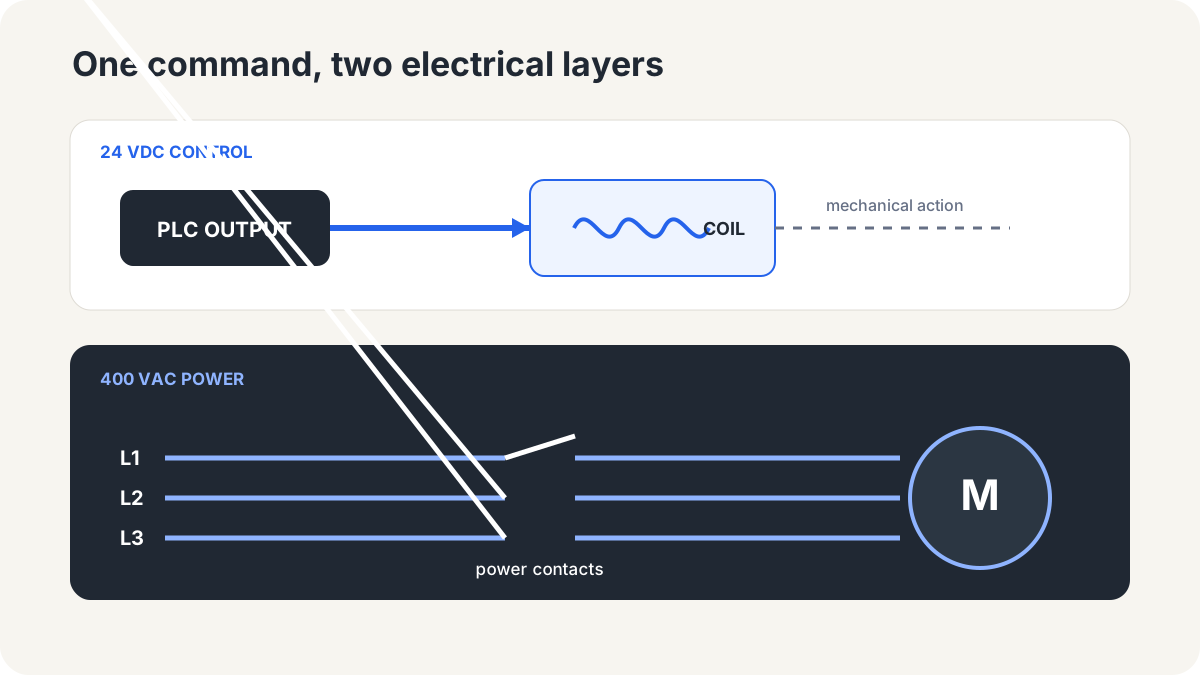
This is a central automation principle: a small control signal manages a large power flow through the correct switching device. Safety functions require an architecture appropriate to the risk assessment; an ordinary PLC command alone is not a safety strategy.
Inside a VFD: AC to DC to AC
A VFD does not simply trim the mains sine wave. Its broad energy path is:
AC input → rectifier → DC bus → inverter → variable-frequency AC → motor
The rectifier converts incoming AC to DC. The capacitor-based DC bus stores and smooths energy. Power semiconductors in the inverter switch that bus using PWM to synthesize a controlled three-phase output. Motor inductance helps turn the pulsed voltage into the fundamental current required for torque.
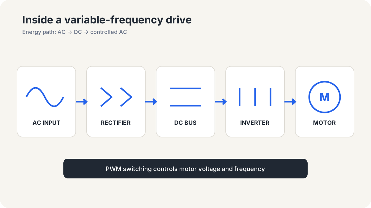
DC-bus capacitors can retain hazardous voltage after input power is removed. Service work must follow the manufacturer’s discharge time and instructions.
0 V, neutral and PE are not the same thing
- 0 V is the return path and measurement reference of a DC circuit.
- N (neutral) is an AC conductor associated with the source neutral point and can carry normal load current.
- PE (protective earth) connects accessible conductive parts to the protective system for fault conditions; it is not intended as a normal load-current path.
A design may bond DC 0 V to PE at a defined point, while another may keep the DC supply floating or isolated. Neutral-to-earth relationships also depend on the supply and earthing arrangement. Possible bonds do not make the three concepts interchangeable. Manufacturer guidance, protection, EMC and the overall system design determine the correct arrangement.
Analog signals: 0–10 V and 4–20 mA
Automation must communicate pressure, temperature, level and speed—not only on/off states.
A 0–10 V interface is simple and common. The receiver scales voltage into an engineering value. Its high input impedance means little current flows, but reference-potential differences and induced voltage noise can affect accuracy.
In a 4–20 mA current loop, 4 mA represents the bottom of the measurement range and 20 mA the top. The 4 mA “live zero” makes a zero reading distinguishable from 0 mA; in some systems, 0 mA helps indicate a broken wire or lost supply. Provided that sufficient loop voltage remains, current signalling is relatively tolerant of cable resistance. Exact fault thresholds and scaling come from the device documentation.
Voltage application map
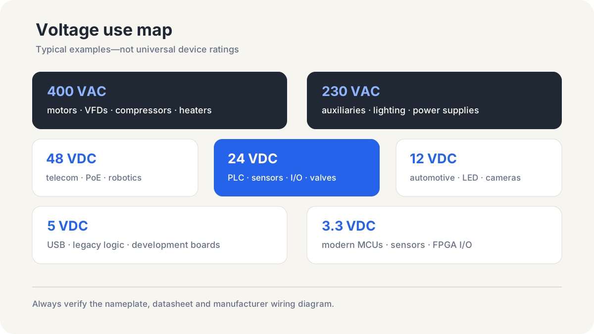
| Voltage level | Common applications |
|---|---|
| 400 VAC | Three-phase motors, VFD/servo feeds, pumps, compressors, larger heaters |
| 230 VAC | Single-phase auxiliaries, cabinet outlets, lighting, power supplies |
| 48 VDC | Telecom, PoE infrastructure, robotics, some servo and distributed-power systems |
| 24 VDC | PLCs, sensors, industrial I/O, relay/contactor coils, valves, some HMIs |
| 12 VDC | Automotive, cameras, LEDs, small motors/fans, selected modules |
| 5 VDC | USB power, classic TTL, Arduino-class boards and peripherals |
| 3.3 VDC | Modern MCUs/SoCs, ESP32, sensors, FPGAs and digital I/O |
This table is not a standard or wiring instruction. Product families often offer several supply variants; the device nameplate, datasheet and manufacturer wiring diagram take precedence.
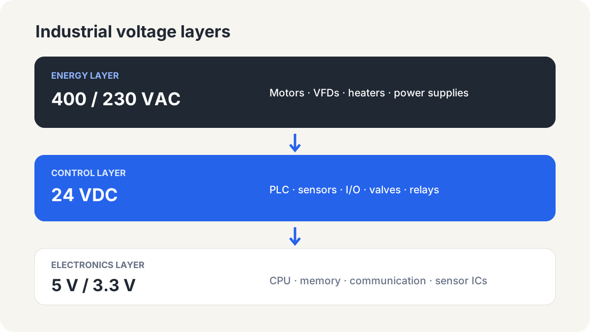
Read automation as three layers
When approaching a cabinet, use this mental model:
- Energy layer—400/230 VAC: Feeds motors, heaters and power converters. Current, short-circuit capability, switching and protection dominate.
- Control layer—24 VDC: Collects field information and controls the machine through PLCs, I/O, relays and valves. Signal integrity and industrial robustness dominate.
- Electronics layer—5 V, 3.3 V and lower: Runs CPUs, memory, communications and precision sensor electronics. Power consumption, logic levels and semiconductor limits dominate.
The boundaries are not absolute; 48 V distribution, 24 V motors and 5 V sensors all exist. The model is still useful because it prompts the right question when tracing a wire: is it moving energy, carrying a command, or representing a chip-level logic state?
Closing perspective
Multiple voltages are not added merely to make automation complicated. 400/230 VAC moves useful power efficiently, 24 VDC provides a robust and manageable field-control layer, and 5 V or 3.3 V serves low-power electronics. Power supplies, drives, relays, contactors, isolation and level interfaces let those layers work together.
The natural next topic is how a sensor presents its 24 V signal to a PLC input: PNP and NPN sensors, PLC input circuits, and sourcing versus sinking logic.