
Connecting 24V Industrial Sensors to 3.3V/5V Microcontrollers
We cover PNP/NPN outputs, isolation, level conversion, and noise management when connecting 24V sensors to 3.3V/5V microcontrollers.
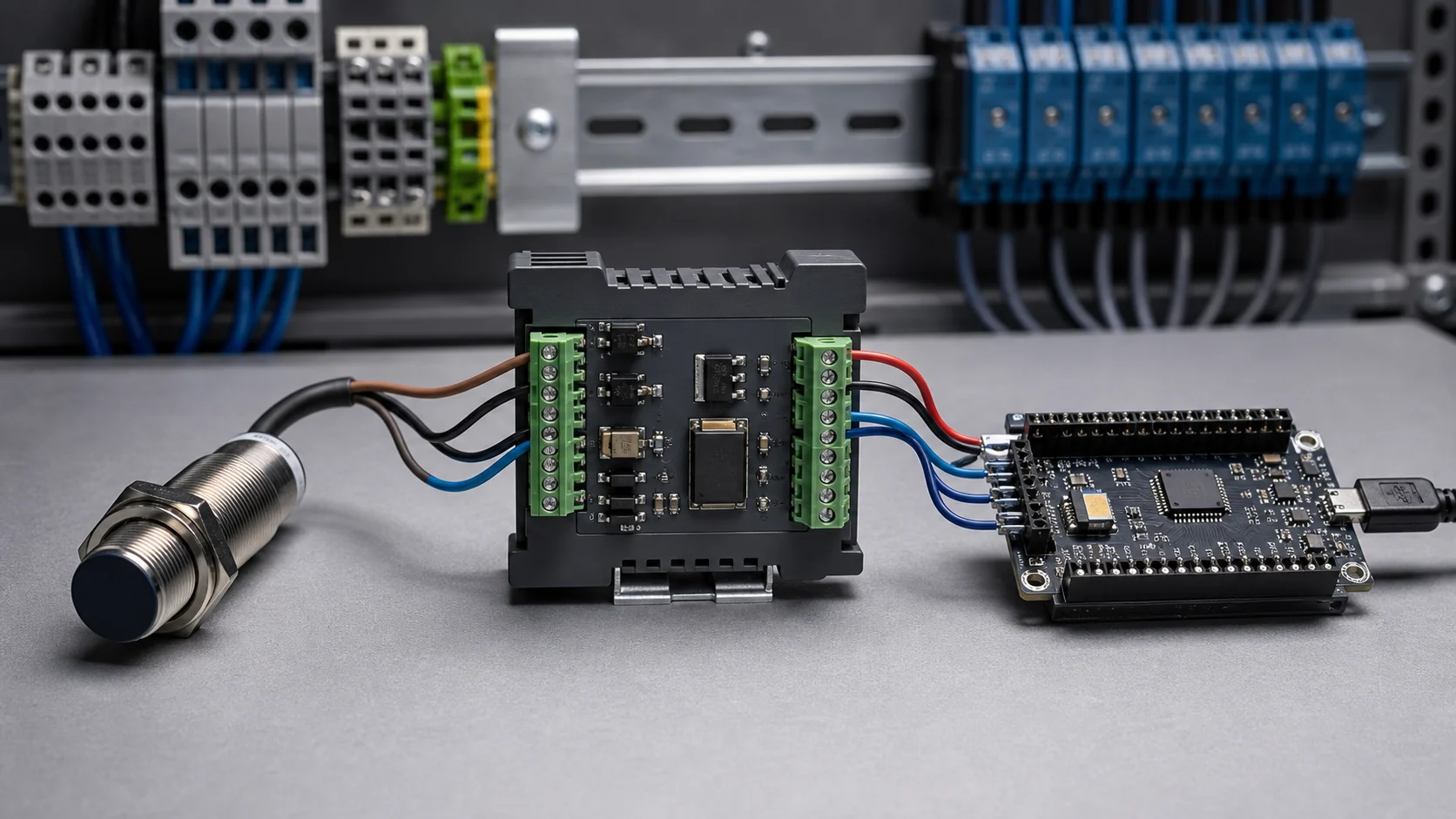
Industrial automation and microcontroller-based projects inevitably meet at some point. On one side, we have 24V proximity, photoelectric, and inductive sensors; on the other, ESP32, STM32, Arduino, and similar controller boards operating at 3.3V or 5V logic levels. When we combine these systems, the main challenge is not powering the sensor but reading its signal at the correct level and with sufficient reliability.
When we want to detect a product on a conveyor, monitor a cylinder’s position, or read a digital state from a machine, the field sensor usually operates from a 24V supply. The GPIO inputs on the microcontroller side accept much lower voltages. Connections that ignore this difference can cause unstable readings or board damage in the long term, even if they appear to work during an initial test. We examine where these voltage layers sit within the wider system in our article on the use of AC and DC in industry and electronics.
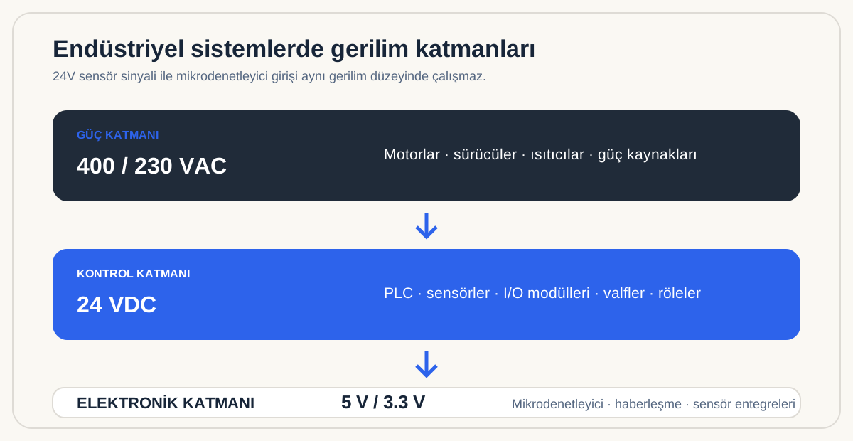
Why do we use different voltages in the same system?
The widespread use of 24VDC control voltage in industrial facilities is not merely a matter of convention. Compared with low-voltage electronic circuits, 24V offers more margin against voltage drop over long cables, works with a large ecosystem of industrial equipment, and provides more robust signaling in noisy environments. For these reasons, many PLC inputs, relay coils, valves, and sensors are designed around 24V.
Microcontroller boards have different priorities. Their processor cores, memory, and communication circuits operate at 3.3V, 5V, or lower levels to support low power consumption and high switching speeds. Both voltage layers are sensible within their own domains. The problem begins when we try to carry a 24V output directly into a low-voltage input without an interface.
There is a substantial difference between the voltage a GPIO pin recognizes as HIGH and the active output of a 24V sensor. Instead of applying that output directly to the pin, we add an interface layer that adapts the voltage and, where necessary, provides electrical isolation.
Important: We do not connect a 24V sensor output directly to a microcontroller GPIO input. We use a level-conversion or isolation stage appropriate for the board and the field conditions.
The connection model: sensor, interface, and controller
Thinking of the connection as three separate sections makes the system easier to evaluate. The first section is the field sensor and its 24V supply. The second is the interface that processes the sensor signal. The final section is the microcontroller’s digital input. The interface is not merely a component that reduces voltage; it is also the first line of defense against noise, wiring errors, and grounding problems.
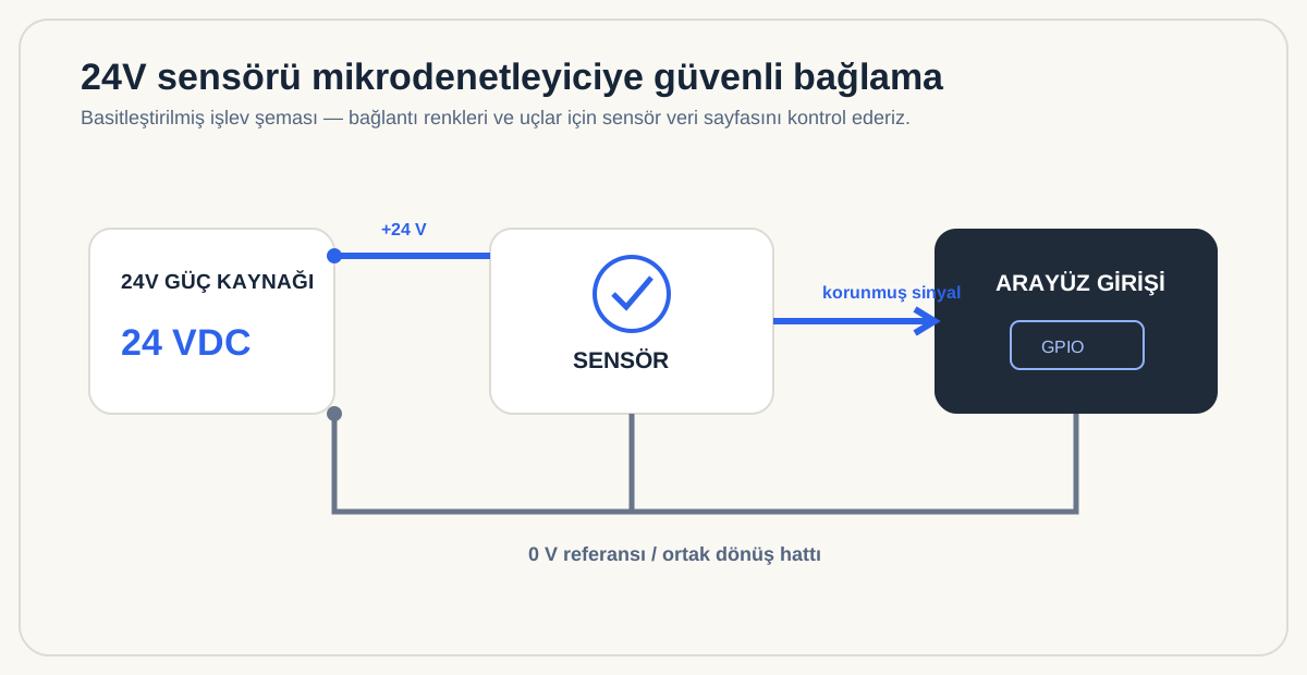
The 0V line in the diagram is particularly important. When we use a non-isolated converter, we establish a common reference between the sensor supply’s 0V line and the controller board’s GND. Without that reference, the microcontroller may not interpret the signal correctly. With an optocoupler-based, genuinely isolated solution, the two sides can remain electrically separate. Randomly joining their GND lines can defeat the benefit of isolation.
We identify the sensor output before choosing a circuit
Industrial sensors can look identical while having different output characteristics. PNP and NPN are the two types we encounter most often. When active, a PNP sensor supplies positive voltage on its output. An NPN sensor instead pulls its output toward 0V. This distinction directly determines which input module we use and how we wire it.
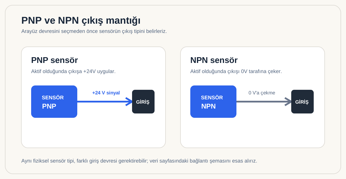
PNP sensors are common in 24V automation applications in Türkiye and Europe. Even so, we do not proceed on the assumption that every sensor is PNP. We check the label on the sensor body and the wiring diagram in its technical documentation. During the same check, we determine whether the sensor operates as normally open (NO) or normally closed (NC). With an NC output, for example, the input may appear active even when there is no target. We interpret the signal accordingly in software.
On common three-wire DC sensors, brown is often used for +24V, blue for 0V, and black for the output signal. We do not treat this convention as a universal wiring rule. Color and pin assignments can vary between manufacturers, on four-wire NO/NC sensors, and on connectorized models, so we verify the manufacturer’s datasheet and wiring diagram.
Which interface method do we choose?
A small bench experiment and a system installed on a machine do not have the same requirements. We evaluate cable length, nearby motors and drives, the enclosure containing the board, maintainability, and possible fault scenarios together.
| Method | Isolation | Complexity | Typical use |
|---|---|---|---|
| Resistor divider | None | Low | Short cables and controlled, low-risk applications |
| Transistor input | None | Medium | Connections that require signal conditioning and additional protection |
| Optocoupler input | Present with a suitable design | Medium | Applications where electrical separation and field robustness matter |
| PLC-style input module | Module-dependent | Medium/high | Multi-channel, panel-mounted, and networked systems |
Level reduction with a resistor divider
The most basic method uses two resistors to reduce a 24V signal to a 5V or 3.3V level. When using a voltage divider, we consider the GPIO pin’s permitted maximum voltage, resistor power ratings, and the tolerance of the 24V supply. We account for the fact that a supply described as “24V” can operate around that nominal value and may reach higher levels.
This method is simple and inexpensive, but it does not provide electrical isolation between the two sides. A divider alone may not offer sufficient protection when we have long field cables, interference from contactors, or a meaningful risk of incorrect wiring. We therefore consider resistor dividers for short-cable, controlled, low-risk applications.
Transistor or protected digital input circuit
Transistor input circuits can convert a 24V signal to a logic level more safely. These designs combine resistors, a transistor, protection diodes, and filtering components where required. We select an input design appropriate for the sensor’s PNP or NPN behavior.
Rather than connecting the sensor directly to the microcontroller pin, the interface circuit conditions the signal. We still keep in mind that this approach normally requires a common 0V reference and does not provide complete galvanic isolation.
Optocoupler input module
As an application moves closer to industrial field conditions, optocoupler input modules can provide a safer path. The sensor signal is connected to the input side of the optocoupler, while its output side presents a logic signal that the microcontroller can read. The signal crosses the barrier through light, allowing electrical separation in a suitable design.
When choosing a ready-made module, we look beyond the mere presence of an optocoupler. We verify that the module is designed for a 24VDC input, supports the required PNP or NPN connection, has a suitable input current, produces an output compatible with 3.3V, and preserves isolation across its power connections. Some modules are designed for 5V output logic, which matters when we use boards with 3.3V GPIO.
PLC-style digital input modules
If we need to read several sensors or install the system in a control panel, we can also consider DIN-rail 24V digital input modules. These modules often provide field-oriented terminal blocks, channel indicators, and protection features. The microcontroller side may communicate over Modbus, RS-485, or another industrial protocol. This approach lets us create a cleaner architecture instead of building a separate small circuit for every sensor.
We do not overlook the difference between 3.3V and 5V
Some boards, such as the Arduino Uno, use 5V logic, while the ESP32, many STM32 models, and boards such as the Raspberry Pi Pico use 3.3V logic. We do not generalize from the board family alone; we check the permitted maximum GPIO input voltage in the documentation for the specific board and microcontroller. Applying 5V to a 3.3V input that is not 5V-tolerant also presents a risk.
We therefore select the interface module’s output to match our board. If the module has an open-collector or open-drain output, it may be possible to operate it on the 3.3V side with a suitable pull-up resistor. If the module actively drives 5V, a 3.3V board needs an additional, appropriate level-conversion stage.
In practice, supply voltage and signal level are not the same concept. A development board may receive 5V through USB while its processor inputs operate at 3.3V. Rather than looking only at the board’s power input, we examine the GPIO electrical specifications.
Wiring and electromagnetic interference
A sensor connection that works reliably on a bench may behave differently beside a machine. Variable-frequency drives, servo drives, contactors, and high-current conductors generate electromagnetic interference. Running sensor wiring parallel to motor power cables over a long distance can cause false transitions in low-level signals.
We therefore route sensor cables separately from power cables wherever possible. For long distances, we can evaluate shielded cable and an appropriate shielding arrangement. Rather than placing the interface far from the microcontroller without consideration, we deliberately choose where the field-side 24V signal will be converted to a lower voltage. Clear wiring, labeling, and terminal blocks inside the panel also reduce maintenance errors.
Filtering short transitions in the microcontroller software is useful as well. Although a sensor output is nominally digital, mechanical vibration, cable effects, or environmental noise can create very brief changes. We obtain a more stable reading by checking the input over several consecutive cycles, accepting it only after it remains stable for a defined period, or using event-based timing logic.
Checks we perform before commissioning
After completing the wiring, we do not use the microcontroller as the first point of verification. We first measure the sensor supply voltage, then use a multimeter to check the sensor output in its active and inactive states. For a PNP sensor, we observe whether the output approaches +24V when the target is detected. For an NPN sensor, we check whether the output is pulled toward 0V.
Next, we measure the interface output on the microcontroller side. When using a 3.3V board, we confirm that this level does not exceed the limit stated in the board’s datasheet. Initially monitoring only the input state through a serial port or status LED lets us verify the signal before enabling the machine’s other functions.
Our checklist consists of the following steps:
- We verify the sensor supply voltage and output type.
- We check the PNP/NPN and NO/NC information in the datasheet.
- We review the interface’s compatibility with a 24V input and 3.3V/5V output.
- We determine whether a common 0V connection is required.
- If isolation is used, we confirm that GND connections do not defeat it.
- We measure the sensor and interface outputs with a multimeter first.
- We match the active/inactive logic in software to the sensor’s actual behavior.
With this approach, we can combine 24V industrial sensors and low-voltage microcontroller boards in a safer, clearer, and more maintainable system.